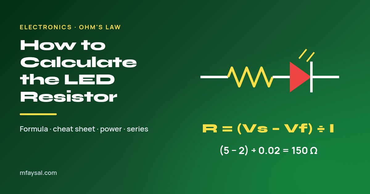
To calculate the resistor for an LED, subtract the LED's forward voltage from the supply voltage and divide by the current you want: R = (Vs − Vf) ÷ I. For a red LED (about 2 V) on a 5 V supply at 20 mA, that's (5 − 2) ÷ 0.02 = 150 Ω. If the answer isn't a standard value, round up to the next one.
That one formula is just Ohm's law applied to the voltage left over after the LED takes its share. The details that cause trouble are knowing the right forward voltage, picking a sensible current, choosing a real resistor value and making sure the resistor can handle the heat.
This guide works through each step with real numbers and ends with a cheat sheet for common supplies. To check any of the maths, the Ohm's law calculator solves for voltage, current or resistance.
In this guide:
- Why an LED needs a resistor
- The LED resistor formula
- Finding the forward voltage and current
- Worked example: a red LED on 5 V
- Worked example: a white LED on 3.3 V
- Choosing a standard resistor value
- Check the resistor's power rating
- LED resistor cheat sheet
- Several LEDs: series or parallel?
- Testing it with an Arduino
- Common mistakes to avoid
- Frequently asked questions
Why an LED needs a resistor
An LED isn't like a light bulb. Once the voltage across it reaches its forward voltage, its resistance drops sharply and it will draw as much current as the supply allows. Without something to limit that current, it overheats and burns out, sometimes in a fraction of a second.
A resistor in series sets the current. The LED takes roughly its forward voltage, the resistor takes the rest, and Ohm's law (V = I × R) fixes how much current flows through both.
SparkFun's beginner guide to light-emitting diodes puts it simply: brightness depends on current, and too much current destroys the LED. The resistor is what keeps you on the right side of that line.
One exception: some LEDs are sold with a built-in resistor, and coin-cell "throwies" rely on the battery's own internal resistance. For a normal LED on a bench supply, an Arduino or a USB power bank, you need the resistor.
The LED resistor formula
Here's the formula and what each part means:
R = (Vs − Vf) ÷ I
- R is the resistor value in ohms (Ω).
- Vs is the supply voltage, for example 5 V from USB or an Arduino pin.
- Vf is the LED's forward voltage, the voltage it drops when lit.
- I is the LED current in amps. Remember that 20 mA = 0.020 A and 10 mA = 0.010 A.
The unit conversion is where most mistakes happen. If you divide by 20 instead of 0.020, you'll get 0.15 Ω instead of 150 Ω, and the LED will be gone the moment you power it up.
A handy shortcut: if you keep the voltage in volts and the current in milliamps, the answer comes out in kilohms. (5 − 2) ÷ 20 mA = 0.15 kΩ, which is 150 Ω.
Finding the forward voltage and current
The best source is the LED's datasheet. Look for forward voltage (Vf), usually given as typical and maximum, and continuous forward current (If), often 20 mA for a standard 5 mm indicator LED. Some datasheets also suggest a comfortable operating current, such as 16 to 18 mA.
If you don't have a datasheet, these typical values are a reasonable starting point for standard indicator LEDs:
| LED colour | Typical forward voltage | Value to use in calculations |
|---|
| Infrared | About 1.2 to 1.6 V | 1.5 V |
| Red | About 1.8 to 2.2 V | 2.0 V |
| Orange or yellow | About 2.0 to 2.2 V | 2.1 V |
| Green (older, yellow-green) | About 2.0 to 2.4 V | 2.2 V |
| Green (bright, true green) | About 2.8 to 3.4 V | 3.0 V |
| Blue, white, pink, UV | About 2.8 to 3.4 V | 3.0 V |
These ranges are approximate and vary by manufacturer, so treat them as a guide rather than a specification. When unsure, use a slightly lower Vf in the calculation. That gives a slightly larger resistor and a slightly lower current, which errs on the safe side.
As for current, you rarely need the full 20 mA. Modern LEDs are bright at 5 to 10 mA, and running cooler extends their life and saves battery.
Worked example: a red LED on 5 V
You want to light a red LED from an Arduino Uno's 5 V pin.
- Supply voltage: Vs = 5 V.
- Forward voltage of a red LED: Vf ≈ 2.0 V.
- Target current: 20 mA = 0.020 A.
- Voltage across the resistor: 5 − 2 = 3 V.
- Resistance: 3 ÷ 0.020 = 150 Ω.
150 Ω is a standard value, so you can use it as is. But many makers would use 220 Ω or 330 Ω instead. Here's what those give on the same circuit:
| Resistor | Current (5 V, red LED) | Result |
|---|
| 150 Ω | 20.0 mA | Full rated brightness |
| 220 Ω | 13.6 mA | Bright, a little cooler |
| 330 Ω | 9.1 mA | Clearly bright indicator, long life |
| 470 Ω | 6.4 mA | Softer glow |
| 1 kΩ | 3.0 mA | Dim but visible |
That's why 330 Ω is a popular "safe default" for 5 V hobby circuits: it's hard to damage anything with it, and most LEDs still look bright.
Worked example: a white LED on 3.3 V
3.3 V boards such as the Raspberry Pi GPIO pins, ESP32 and many newer microcontrollers leave very little headroom for blue and white LEDs.
- Vs = 3.3 V, Vf ≈ 3.0 V for a white LED.
- Voltage left for the resistor: 3.3 − 3.0 = 0.3 V.
- At 10 mA: 0.3 ÷ 0.010 = 30 Ω, so round up to 33 Ω.
The problem is that with only 0.3 V across the resistor, a small change in the LED's real forward voltage makes a big difference to the current. If this particular LED is 2.9 V, the current jumps to about 12 mA; at 3.2 V it falls to about 3 mA. The brightness becomes unpredictable from one LED to the next.
For a red LED on the same 3.3 V supply, there's much more margin: (3.3 − 2.0) ÷ 0.010 = 130 Ω, rounded up to 150 Ω, giving about 8.7 mA. If you need consistent white or blue LEDs on 3.3 V, power them from 5 V through a transistor switched by the GPIO pin, and keep each microcontroller pin well within the current its datasheet allows.
Choosing a standard resistor value
Resistors come in preferred values, not every possible number. The most common range for hobby kits is the E12 series, which repeats these 12 values in every decade:
10, 12, 15, 18, 22, 27, 33, 39, 47, 56, 68, 82
So the available values near 300 Ω are 270 Ω, 330 Ω and 390 Ω, and near 1,000 Ω you have 820 Ω, 1 kΩ and 1.2 kΩ.
The rule is to round up to the next standard value. A bigger resistor means slightly less current, which is safe. Rounding down means slightly more current than you planned, which can push the LED past its rating.
Resistors also have a tolerance, commonly ±5% or ±1%. A 150 Ω, 5% resistor can be anything from 142.5 Ω to 157.5 Ω, which barely changes the LED current. Tolerance only matters when you're running close to the LED's maximum.
Check the resistor's power rating
The resistor turns the extra voltage into heat. If that heat exceeds its rating, it will get hot, drift in value or fail. Calculate it with:
P = I² × R or equivalently P = (Vs − Vf) × I
For the 5 V red LED at 20 mA: P = 3 V × 0.020 A = 0.06 W. A standard 0.25 W (¼ W) resistor handles that easily.
Higher supply voltages change the picture. A red LED on 12 V at 20 mA needs (12 − 2) ÷ 0.020 = 500 Ω, rounded up to 560 Ω, and the resistor dissipates about 0.18 W. That's still under ¼ W, but closer than you'd like. A common rule of thumb is to pick a resistor rated for at least twice the power it will actually dissipate, so a ½ W part is the more comfortable choice there.
If you see the resistor's power climbing towards 0.5 W or more, it's a sign that a resistor is the wrong approach. Use several LEDs in series to soak up more of the voltage, or use a constant-current LED driver.
LED resistor cheat sheet
These values use a red LED at 2.0 V and a blue or white LED at 3.0 V, rounded up to the next E12 value. Always check against your LED's datasheet.
| Supply | Red at 20 mA | Red at 10 mA | Blue/white at 20 mA | Blue/white at 10 mA |
|---|
| 3.3 V | 68 Ω | 150 Ω | 15 Ω (not recommended) | 33 Ω (marginal) |
| 5 V | 150 Ω | 330 Ω | 100 Ω | 220 Ω |
| 9 V | 390 Ω | 820 Ω | 330 Ω | 680 Ω |
| 12 V | 560 Ω | 1 kΩ | 470 Ω | 1 kΩ |
For 9 V and 12 V supplies, check the power rating as described above. At 12 V and 20 mA, the resistor dissipates close to 0.2 W.
To read resistors in your kit, these are the colour bands for common four-band values:
| Value | Colour bands (4-band) |
|---|
| 100 Ω | Brown, black, brown, gold |
| 150 Ω | Brown, green, brown, gold |
| 220 Ω | Red, red, brown, gold |
| 330 Ω | Orange, orange, brown, gold |
| 470 Ω | Yellow, violet, brown, gold |
| 1 kΩ | Brown, black, red, gold |
The gold band means ±5% tolerance. If in doubt, measure with a multimeter.
Several LEDs: series or parallel?
In series, LEDs share one current, and their forward voltages add up. Two red LEDs in series drop about 4 V, so on a 12 V supply at 20 mA you'd need (12 − 4) ÷ 0.020 = 400 Ω, rounded up to 470 Ω. The total forward voltage must stay below the supply voltage, with some headroom, or the LEDs won't light reliably.
In parallel, give every LED its own resistor. Don't share one resistor between several parallel LEDs. Because no two LEDs have exactly the same forward voltage, the one with the lowest Vf will hog the current, run hot and fail first. Then the others share its current and fail in turn.
A practical approach for, say, six white LEDs on 12 V is two strings of three in series (about 9 V per string), each string with its own resistor: (12 − 9) ÷ 0.020 = 150 Ω.
If you're laying out holes for a panel or enclosure, our inches to mm converter helps when US parts lists give LED sizes in fractions of an inch.
Testing it with an Arduino
Once you've chosen the resistor, a blink sketch is the easiest test. Wire the Arduino pin to the resistor, the resistor to the LED's longer leg (the anode), and the LED's shorter leg (the cathode) to GND.
const int LED_PIN = 9;   // any digital pin

void setup() {
  pinMode(LED_PIN, OUTPUT);
}

void loop() {
  digitalWrite(LED_PIN, HIGH);
  delay(500);
  digitalWrite(LED_PIN, LOW);
  delay(500);
}
The resistor can go on either side of the LED; the current is the same in a series circuit. If the LED doesn't light, flip it round. LEDs only conduct one way, and a reversed LED simply stays dark rather than breaking.
To dim the LED without changing the resistor, use analogWrite(LED_PIN, 64) on a PWM pin. PWM switches the LED on and off quickly, so the peak current is still set by the resistor.
Common mistakes to avoid
- Forgetting to convert milliamps. Divide by 0.020, not 20, unless you want the answer in kilohms.
- Rounding down. Always round up to the next standard resistor value.
- Sharing one resistor across parallel LEDs. Give each LED, or each series string, its own resistor.
- Ignoring power on higher voltages. Check P = (Vs − Vf) × I whenever the supply is 9 V or more.
- Driving LEDs at maximum current. 20 mA is a limit, not a target. 5 to 10 mA is plenty for most indicators.
- Assuming every white LED is identical. Forward voltage varies, which matters most when the supply is only slightly higher than Vf.
Get those right and LED circuits become one of the most forgiving things in electronics.
Frequently asked questions
How do I calculate the resistor value for an LED?
Subtract the LED's forward voltage from the supply voltage, then divide by the current in amps: R = (Vs − Vf) ÷ I. For a red LED at 2 V on 5 V at 20 mA, (5 − 2) ÷ 0.02 = 150 ohms.
What resistor do I need for an LED on 5V?
For a red LED at 20 mA you need about 150 ohms, and for a blue or white LED about 100 ohms. Many people use 220 or 330 ohms for a slightly dimmer but safer and longer-lasting LED.
Can I use a 220 ohm resistor for an LED?
Yes, on a 5 V supply a 220 ohm resistor gives roughly 13.6 mA through a red LED and about 9 mA through a white LED. Both are safe and bright for indicator use.
What happens if I use an LED without a resistor?
Current rises until the LED overheats, often destroying it almost instantly. It can also overload a microcontroller pin. Always use a series resistor unless the LED has one built in.
Should I round the resistor value up or down?
Round up to the next standard value. A slightly larger resistor gives slightly less current, which is safe, while rounding down can push the LED above its rated current.
Does it matter which side of the LED the resistor goes on?
No. In a series circuit the same current flows through every part, so the resistor can go between the supply and the anode or between the cathode and ground.
Can several LEDs share one resistor?
Only if the LEDs are in series. For LEDs in parallel, give each one its own resistor, because small differences in forward voltage make one LED take most of the current.
What power rating does an LED resistor need?
Work out P = (Vs − Vf) × I. Most 5 V indicator circuits dissipate under 0.1 W, so a quarter-watt resistor is fine. On 12 V supplies, check the figure and choose a resistor rated for about twice the result.
Last checked: 19 October 2026. Figures, settings and guidance can change, so confirm anything important with the sources linked above.